COMSOL Acoustics Consulting
PhysAI can use the power of COMSOL Multiphysics for advanced acoustics simulations, from biomedical and flow sensors applications to room acoustics and electromagnetic transducers.
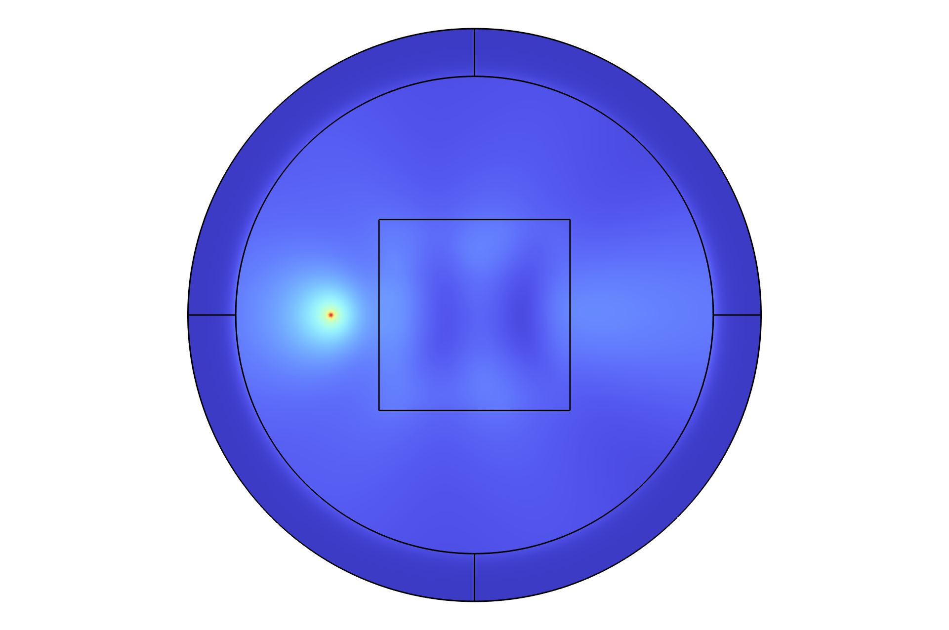
Acoustic Imaging
Acoustic imaging involves reconstructing an internal image of an object or medium by analyzing how sound waves propagate through it. The process typically begins with a reference image—either a known structure or an idealized baseline—used to benchmark the reconstruction. Using a Radon transform, this image can be converted into a sinogram, which represents the set of all possible line integrals (or projections) of the acoustic field at different angles. While traditional sinograms are often generated analytically from the reference image, a more powerful approach uses a full-wave acoustic solver to numerically simulate the propagation of sound and capture the pressure data at various detector positions around the domain. This simulated data can then be used to construct an empirical sinogram. By comparing the sinograms generated from the reference image and the full-wave solver, one can identify discrepancies that reveal subtle structural or material differences within the medium—enabling robust defect detection, anomaly localization, or inverse modeling.
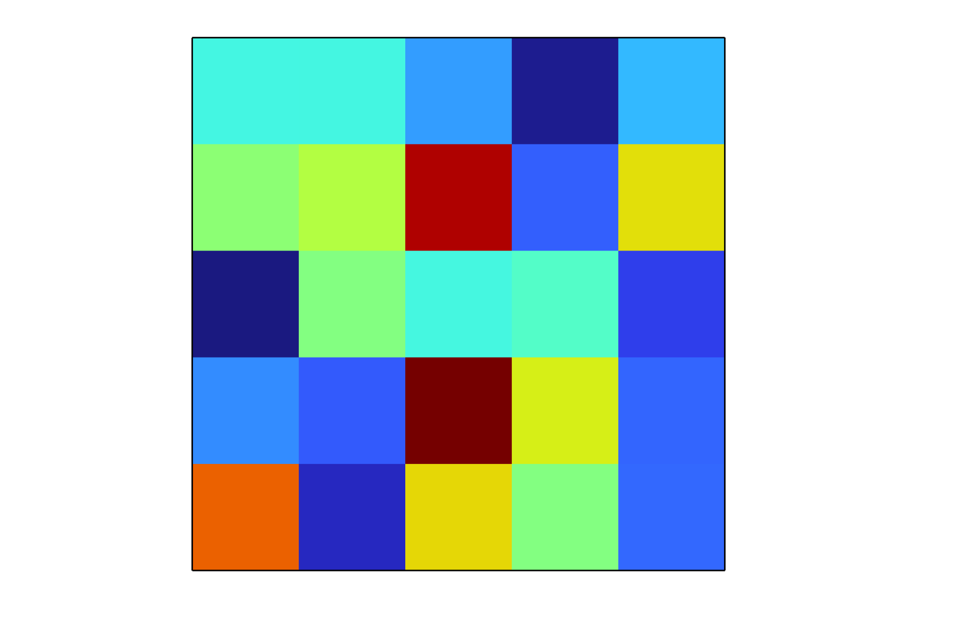
The variation of the sinogram with the rotation angle of the scanned object can be seen below.
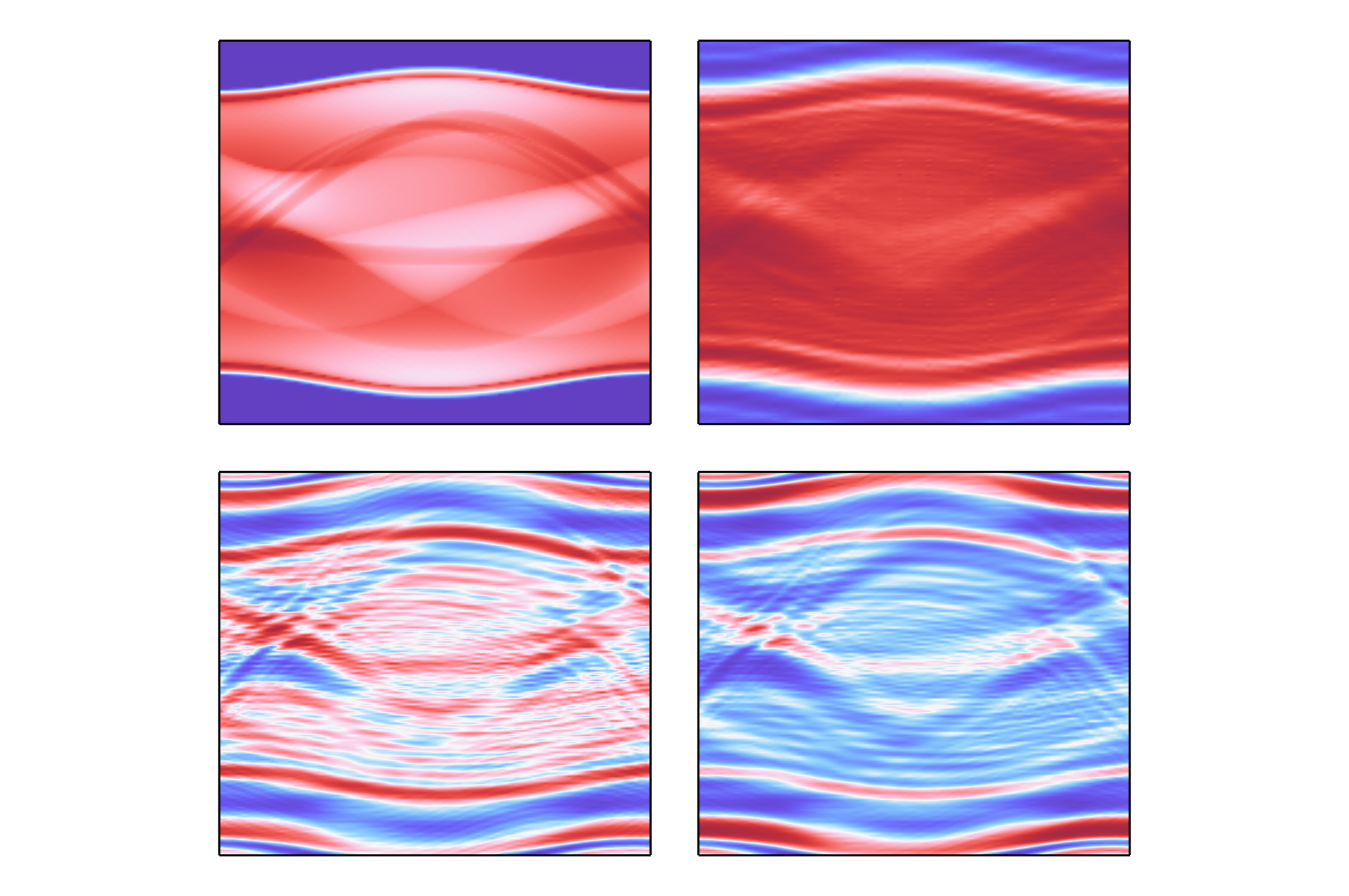
- Top Left (Radon Transform Baseline): This is the idealized sinogram derived from the Radon transform under the assumption of straight-line, lossless ray paths. As expected, the features appear smooth and sinusoidal, with high contrast and minimal noise. This serves as a reference case, showing the expected projection data when assuming perfect transmission, constant material properties, and no diffraction or scattering effects.
- Top Right (Full-Wave, 1 dB/cm Attenuation, Matched c and ρ): In this scenario, attenuation is included, but the acoustic impedance (sound speed and density) is uniform. Compared to the Radon transform, the overall structure of the sinogram is preserved, but with reduced contrast and some blurring — especially in the high-attenuation regions. The dominant features remain recognizable, suggesting attenuation primarily scales the amplitude rather than distorting the geometric content of the sinogram.
- Bottom Left (Full-Wave, No Attenuation, ±50 m/s Sound Speed Variation): This case introduces heterogeneity in the sound speed while keeping attenuation at zero. The sinogram now exhibits pronounced wavefront distortions and high-frequency oscillations, likely due to wave refraction and scattering caused by sound speed gradients. The symmetry and sinusoidal patterns of the Radon case are visibly disrupted, indicating that sound speed variation significantly alters the path and phase of acoustic waves, challenging the straight-line assumption of Radon geometry.
- Bottom Right (Full-Wave, Both Attenuation and Sound Speed Variation): This is the most realistic and complex simulation, incorporating both attenuation and heterogeneous media. The resulting sinogram is the most distorted, showing combined effects of amplitude loss and phase distortion. The features are less sharp, and interference-like patterns suggest a superposition of refracted and attenuated waves. This closely mimics what might be expected in real-world imaging scenarios such as medical ultrasound or seismic tomography, where both effects are present.
Multiphysics Modeling in Acoustic Medical Imaging Systems
While image reconstruction often uses simplified acoustic models, the surrounding hardware and signal pathways rely on rich multiphysics interactions that benefit from detailed simulation:
- Sensor Response Modeling: Acoustic detectors (e.g., piezoelectric or capacitive MEMS microphones) convert pressure into voltage, heat flux, or mechanical deformation. Modeling the coupled electromechanical or thermoacoustic response is essential for calibration and sensitivity optimization.
- Emitter–Tissue Coupling: Ultrasound transducers must efficiently transmit acoustic energy into tissue. This involves simulating structural vibrations, acoustic impedance matching, and gel or membrane coupling layers to reduce reflection losses at interfaces.
- Thermal and Safety Analysis: Prolonged or high-intensity insonification can raise local tissue temperature. Full bioheat transfer modeling predicts temperature rise, guiding compliance with safety standards (e.g., FDA thermal indices).
- Packaging and Crosstalk: In array systems, nearby elements can mechanically or electrically interfere. Modeling vibration isolation, thermal drift, and EM shielding helps maintain image fidelity.
- Fluid–Structure Interaction: In some modalities (e.g., intravascular ultrasound or photoacoustics), dynamic blood flow or tissue deformation must be captured to predict system performance in vivo.
COMSOL Multiphysics is well-suited for simulating these complex, coupled domains, bridging the gap between raw measurement physics and clinical imaging performance.
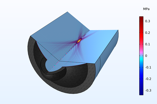
Focused Ultrasound for Precision Targeting
Focused ultrasound (FUS) uses converging acoustic waves to target tumors or kidney stones noninvasively. COMSOL simulates the pressure field and heat deposition, solving the Helmholtz equation for wave propagation:
where \( k = \omega / c_0 \) is the wavenumber, and \( \omega \) is the angular frequency. By optimizing transducer design and focusing parameters, FUS achieves pinpoint accuracy, minimizing damage to surrounding tissues.
Unfocused ultrasound powers diagnostic imaging by emitting broad acoustic waves and interpreting reflected signals. COMSOL models wave scattering and attenuation, enabling rapid simulation of imaging scenarios. Integrating artificial intelligence (AI) enhances this process, accelerating image reconstruction through machine learning algorithms trained on simulated datasets.
Shockwave Therapy in Biomedical Engineering
Shockwave therapy leverages high-energy acoustic waves to treat conditions like musculoskeletal disorders. The steep pressure front of a shockwave arises due to nonlinear effects, characterized by a high B/A nonlinearity coefficient in the governing equations. COMSOL Multiphysics models these phenomena using the nonlinear acoustics module, solving:
Here, \( p \) is the acoustic pressure, \( c_0 \) is the speed of sound, \( \rho_0 \) is the medium density, and \( B/A \) quantifies nonlinearity. This steep front enhances therapeutic efficacy by delivering concentrated energy to targeted tissues.
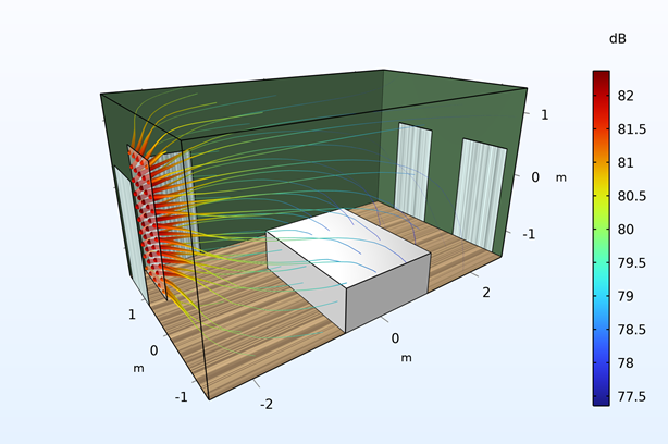
Room Acoustics Optimization
COMSOL Multiphysics excels in simulating room acoustics, addressing both external noise ingress and internal sound quality. Below, we explore key aspects of noise propagation and suppression.
External Noise Propagation into a Room
External noise enters rooms through multiple pathways, each modeled in COMSOL:
- (a) Direct Transmission: Sound waves pass
through walls or windows, governed by the transmission loss
equation:
\[ T_L = 10 \log_{10} \left( \frac{I_i}{I_t} \right) \]where \( I_i \) and \( I_t \) are incident and transmitted intensities.
- (b) Structure-Borne Noise: Vibrations from external sources (e.g., traffic) travel through building structures, modeled via coupled structural-acoustic simulations.
- (c) Flanking Noise and Paths: Sound bypasses barriers via indirect routes (e.g., ceilings or ducts), requiring detailed geometric modeling in COMSOL.
Internal Noise Suppression Methods
Internal noise perception arises from direct sound and subsequent reflections, including flutter echoes. The sound pressure level at a point is:
where \( p_{\text{rms}} \) is the root-mean-square pressure, and \( p_{\text{ref}} = 20 \, \mu\text{Pa} \). Reflections amplify perceived loudness, but COMSOL helps design suppression strategies:
- Low Frequencies (20-200 Hz): Use thick, porous absorbers (e.g., bass traps) to dampen standing waves.
- Mid Frequencies (200-2000 Hz): Install diffusers or mid-range absorbers to scatter and absorb speech-range noise.
- High Frequencies (>2000 Hz): Apply thin, reflective surfaces or lightweight absorbers to reduce sharpness and flutter echoes.
By simulating direct and reflected paths, COMSOL optimizes room layouts and materials for a balanced acoustic environment.